Intermediate • aerodynamics • airfoil • anderson • intermediate • core
Airfoil Fundamentals: How Wings (and Fins) Create Lift
Learning Objectives
- Explain the Kutta condition and why it produces circulation around an airfoil
- Use thin airfoil theory to predict lift slope and zero-lift angle from camber
- Understand how finite aspect ratio creates induced drag via wingtip vortices
- Calculate the effect of aspect ratio and taper on lift slope and induced drag using lifting-line theory
Core Explanation
Lift on a wing is not primarily 'the air on top has farther to go so it goes faster.' That story is a useful approximation at best and actively misleading at worst.
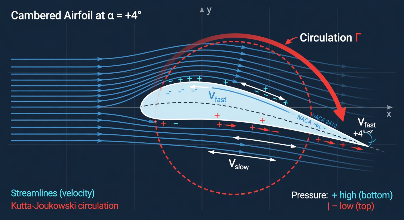
The real mechanism is circulation. At the sharp trailing edge of any well-designed airfoil, the flow must leave smoothly (the Kutta condition). This forces the air to develop a net circulation Γ around the entire wing. By the Kutta-Joukowski theorem, lift per unit span is simply L' = ρ∞ × V∞ × Γ.
Camber (the gentle curvature of the airfoil) changes the effective angle that the airfoil 'sees.' A cambered airfoil produces positive lift even at zero geometric angle of attack because the trailing-edge condition requires circulation.
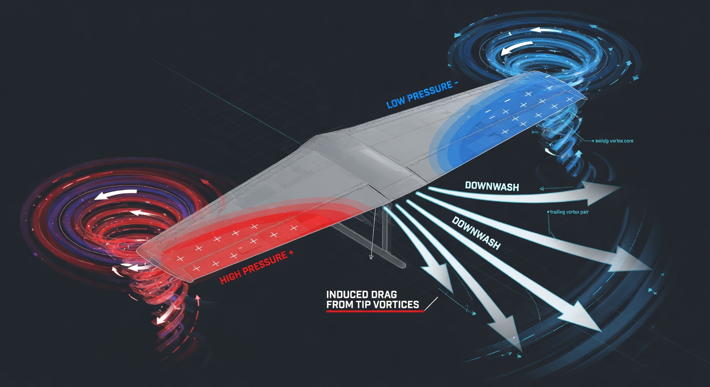
For a real finite wing (every wing has tips), the high pressure on the bottom leaks around the tip toward the low pressure on top. This creates a pair of strong, counter-rotating tip vortices that trail for miles behind a large aircraft. The vortices induce a downward velocity component (downwash) in the flow behind the wing. The local flow vector is tilted; therefore the lift vector, which is always perpendicular to the local flow, is tilted backward. That rearward component is induced drag.
Induced drag scales with CL² / (π × AR × e) where AR is aspect ratio and e is Oswald efficiency. High aspect ratio wings (long and skinny) have far less induced drag for the same total lift because the tip vortices represent a smaller fraction of the span. Low aspect ratio surfaces (rocket fins, delta wings, grid fins) pay a high induced-drag penalty but buy structural strength and control authority.
The Airfoil & Finite Wing Lab lets you change camber, alpha, AR, and taper in real time and watch Cl, CL, CDi, and the pressure distribution update instantly — exactly the quantities used in Anderson Chapters 4–5.
Visual Explanations
Streamlines around a cambered airfoil at positive alpha showing higher velocity (denser streamlines) on top, plus a superimposed circulation arrow around the airfoil.
Engineering visualization
3D view of finite wing with tip vortices rolling up from high pressure below to low pressure above, trailing behind as helical vortices, with downwash in the wake.
Engineering visualization
These diagrams were generated specifically to illustrate the concepts. Open the linked simulator to interact with the same physics in real time.
Interactive Exploration
Theory becomes intuition when you change the variables yourself. The simulator below implements the exact equations and flow physics described above.
Launch airfoil wing Simulator →Try These Experiments in the Simulator
- Start with the symmetric NACA 0012 at α = 0°. Cl should be essentially zero. Now load the cambered 2412 at the same α = 0°. Cl jumps positive immediately — camber alone produces lift.
- Fix α = 4° and sweep AR from 4 (stubby fin) to 12 (high-performance wing). Watch CL rise and CDi fall. This is the direct penalty of low aspect ratio.
- Inspect the Cp distribution. The huge negative pressure peak near the leading edge on the upper surface is where most of the lift is generated. Move the peak and you move the aerodynamic center.
- Try a highly tapered planform (taper ratio 0.2). Notice how the lift distribution changes and Oswald efficiency drops — real wings are tapered for structural reasons but pay an induced-drag price.
Return here after experimenting — the reflection questions will make more sense.
Common Misconceptions
- Equal transit time (longer path over the top) fully explains lift — This is a common classroom story but incomplete. Cambered airfoils produce lift at zero alpha with no 'longer path' difference that can explain the circulation.
- Wings only work because of Bernoulli — Bernoulli relates pressure and velocity, but the fundamental reason pressure is lower on top is the circulation required by the Kutta condition. Bernoulli is a consequence, not the root cause.
- Induced drag only matters for gliders and airliners — Every finite wing or fin produces it. For rockets, fins, canards, and grid fins all generate induced drag that affects stability margins, control effectiveness, and trajectory performance.
Real-World Connections
- Falcon 9 grid fins are deliberately low-aspect-ratio, high-induced-drag devices. They are used only during reentry for steering when dynamic pressure is low; they are folded away for ascent.
- Starship’s large body flaps and forward flaps are low-AR control surfaces that trade induced drag for the massive control authority needed in the thin upper atmosphere.
- Competition sailplanes routinely fly aspect ratios of 40–60 specifically to drive induced drag to extremely low levels at the lift coefficients required for efficient thermalling and cruise.
Reflection & Mini-Challenges
- Why does a symmetric airfoil at zero geometric alpha produce zero lift while an otherwise identical cambered airfoil produces positive lift at the same alpha? Use the Kutta condition in your answer.
- If you double the aspect ratio of a wing while holding total lift and dynamic pressure constant, roughly what happens to induced drag? Why is the relationship not simply 1/2?
- You are designing fins for a sounding rocket that must be stable at both low speed (launch) and high speed (supersonic). Would you choose high or low aspect ratio? What are the stability, drag, and structural trade-offs?
Animated Explanations
Why Finite Wings Create Induced Drag
Slow-motion 3D animation of flow under and over a wing tip, showing the roll-up into a vortex and the resulting downwash that tilts lift backward.
Full motion visualization planned for future updates. The static diagrams and live simulators above cover the core dynamics today.
Next Steps
- → In Rocket Forge, add a set of low-AR fins with realistic Cd and watch the effect on max-Q structural loads and on apogee. Then try high-AR fins and compare.
- → Move to the Compressible Flow Lab. At M = 0.8+ the upper-surface pressure distribution you just studied develops a shock. The same airfoil that was gentle subsonically can produce a sudden drag rise.
- → Design a winged recoverable booster in Forge. Optimize AR versus structural mass and hinge moments for a boost-back or RTLS trajectory. The induced drag numbers from the lab become real Δv losses.